US2B Radar
An UltraSonic USB Radar
|
Microcontroller: Microchip PIC18F4550 Sensor: 1x Ultrasonic Range Sensor (Devantech SRF04, e.g. here) Actor: 1x Some old bipolar stepper motor for turning the sensor Video: The radar in action License: 
The source code of this work is licensed under a Creative Commons License. This project is featured on: hackedgadgets.com ccspic.com |
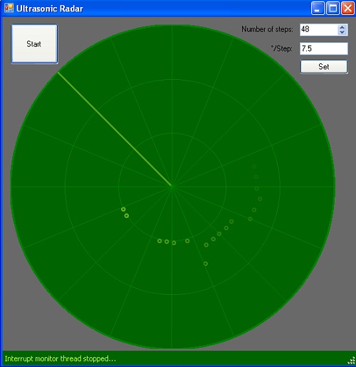 » This is a screen shot of the radar screen application written in C#. The USB communication code for the PIC as well as the application has been taken from the Asynchronous PIC-to-PC USB Interrupt Transfers project by Evan Dudzik. The Visual Studio 2005 project as well as the PIC18F4550 MPLAB project are available here. The PIC is programmed in a way that the stepper motor only advances if the PC has taken the data. This means that one can start and stop the radar easily from within the application using the start/stop button. Also, to support different stepper motors one can/has to specify the number of steps the radar should do before turning back to start position and, for correct visualization on the screen, the degrees per step. For programming the PIC it has to be programmed with the Microchip USB Bootloader, as described by Evan. |
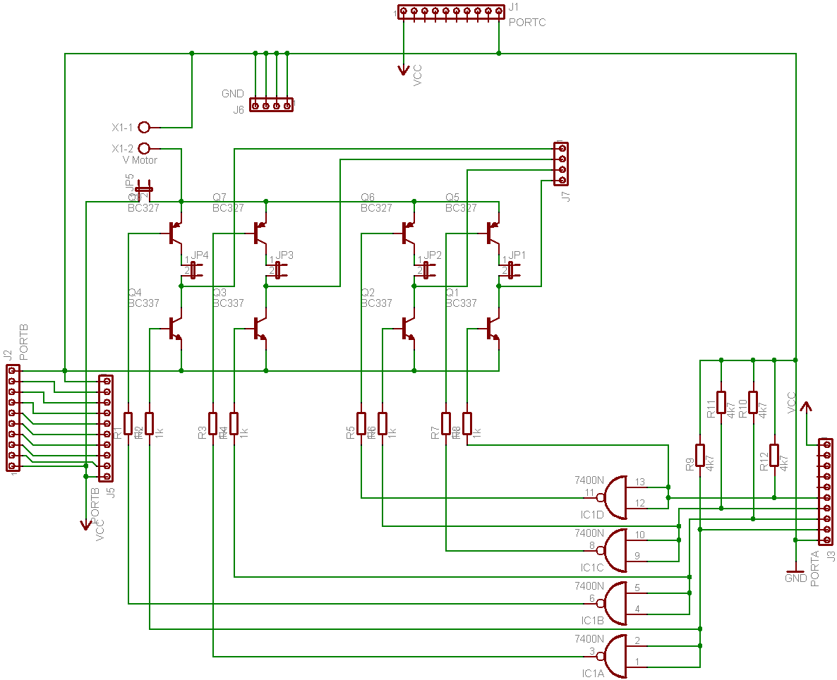 » The circuit for controlling the stepper motor. It is comprised of two H-Bridges and can be used to control bipolar (in my case) and unipolar stepper motors by configuring the jumpers between the transistors accordingly. The PIC controls the motor using PORTA<0:3>. PORTC is only for power supply and mounting the whole thing on one of my prototyping boards (see 1. picture lower board, description coming soon....). PORTB is just passed through from the prototyping board in order to connect the SRF04 range finder. It is simply connected to 5V, GND and PORTB3 (Trigger) and PORTB7 (Echo). |
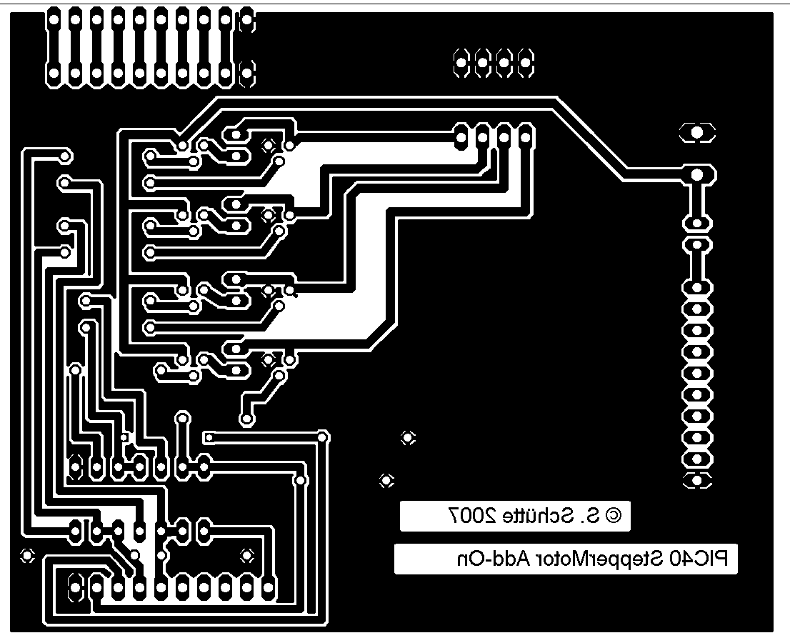 » This is the stepper control board based on the circuit above, seen from the top (non copper side). |
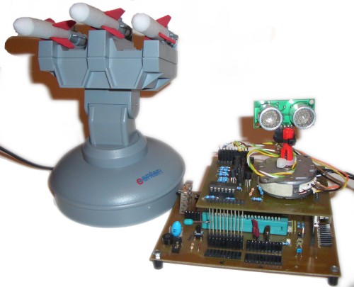 » Some days after I finished working on the radar a friend of mine got a USB Missile Launcher. So the idea was born to combine this with the radar. Luckily there is an excellent project to interface this missile launcher using C# available for free download at: http://code.google.com |
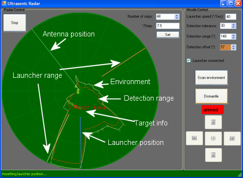 » This picture shows the final application and the meaning of the UI elements. So how does it work? First the radar is started as usual. After the radar has turned around completely, you press "Scan Environment" to let the application know that the detected targets are the normal environment (walls, chairs, etc...). The application automatically subtracts the adjusted "Detection tolerance" from the distance of the detected environment to set the targeting range. This is the area in which targets are detected. Now you press "Arm" to activate the launcher and the detection algorithm. As there is no possibility to find out into which direction the launcher is turned, the application simply instructs the launcher to turn to the left for a certain number of sconds. As this is enough for the launcher to turn around completely the application now "knows" the launcher's position. Of course once in the beginning it has to be adjusted manually according to the radar position. Now, if there is a target within the detection range (the red area) the application turns the launcher to the nearest detected target and fires. Again, as there is no way to determine the launcher's direction the turning time is calculated based on the difference between the launcher and the target direction. If the launcher turns too long or too short, you have to change the value in the "Launcher speed" selector. The adapted Visual Studio 2005 project is available here. The PIC project for the radar is the same as above. |
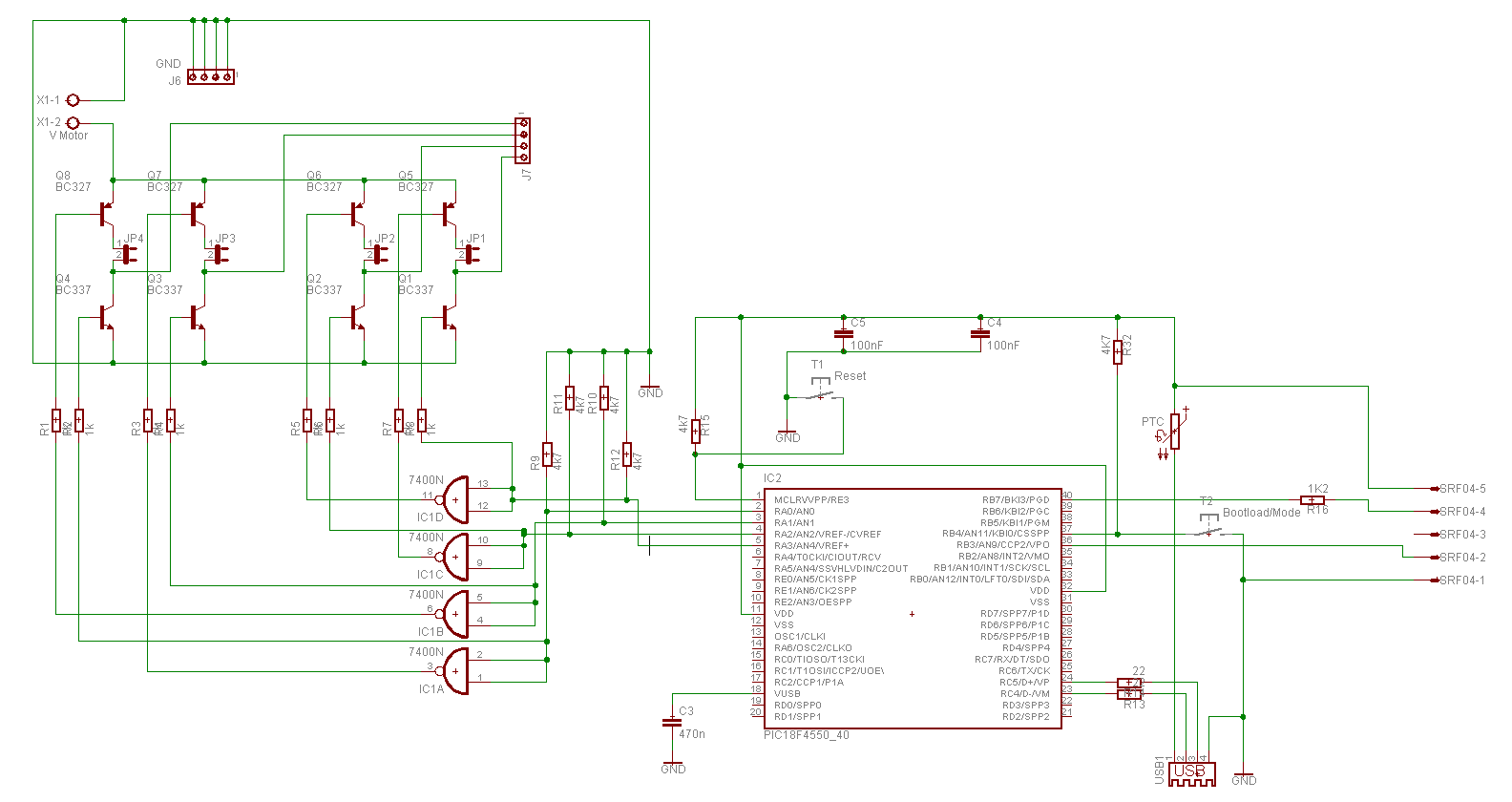 » The above picture shows the complete circuit including the connections to the PIC18F4550 and the SRF04 range finder. A tutorial for setting up the whole stuff can be found here. |