Hexapod
RoboSpider Generation II
|
Microcontroller: PIC18F4550 - The brain PIC18F2680 - Servo controller (up to 14 servos) and motion engine PIC16F628 - SPI-Interface for up to 8 infrared obstacle sensors PIC16F628 - SPI-Interface for TSL 235 light sensors Sensors: 8x infrared sensor Sharp IS471 2x flexible bend sensors as whiskers 4x TSL 235 light to frequency converter for detecting light conditions Actors: 6x 9 gramm micro servos for horizontal leg movement 6x Hitec HS82MG servos for vertical leg movement Video: Spider in action |
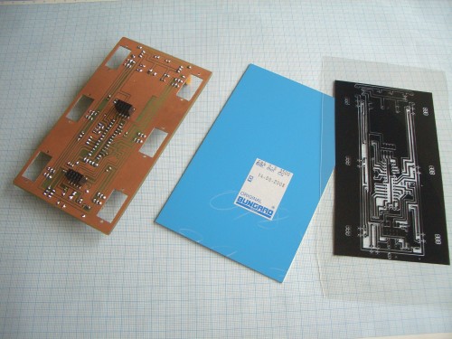 » The basis for this hexapod is a servo board with a PIC18F2680 for controlling up to 14 servos. The above picture shows the printed circuit for exposure of the PCB, a raw PCB and the final PCB with 6 holes for mounting the servos that are used for horizontal leg movement. This PIC will get commands from another PIC via SPI protocol. However, I used a PIC18F2680 because it also has an on board CAN controller. The PCB allows to plug in a suitable CAN controller (e.g. MCP2550) if desired which I might use later. |
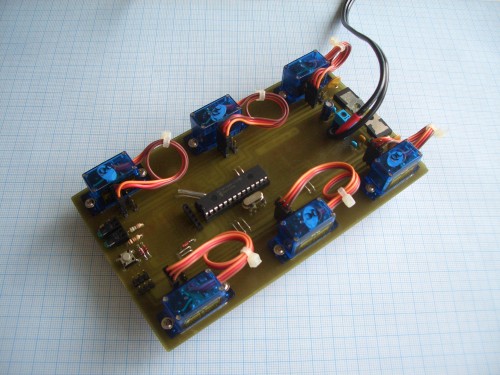 » Here the finished PCB with the 6 servos for horizontal leg movement is shown. On the right you can see two voltage regulators. One supplying 5V (1A) for the PIC (and other devices later on) and the other supplying the servos with 6V (2A). |
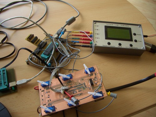 » Programming and testing the servo board using my PIC18F4550 demo board and a logic analyser for debugging the SPI communication. |
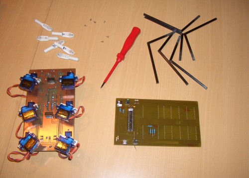 » After mounting the servos for vertical leg movement using aluminium angles, the legs could be mounted. I used carbon fibre pipes for building the legs which are mounted to the servos using some plastic pipes that I heated up and pressed into shape. This picture also shows the second PCB containing a PIC18F2550 with a USB interface. This board shall be used as the "brain" of the spider and can be extended by different sensors (see below). |
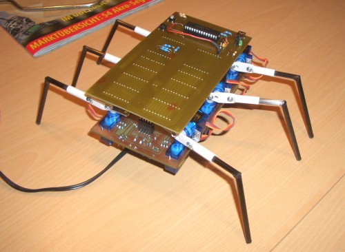 » Here you can see the spider with assembled legs and the "brainboard". |
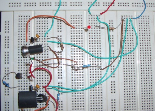 » For navigation I wanted to have some infrared distance sensors which are cheep and easy to use. I found a sensor type that meets these requirements: The ISF 401 form sharp, e.g. available at www.roboter-teile.de. The above picture shows a test setup for these sensors. After the final circuitry had been determined new PCBs could be made. At first I want to start with 8 sensors (2 front, 2 rear and 4 downwards for allowing the spider to stop , e.g. at the rim of a table). |
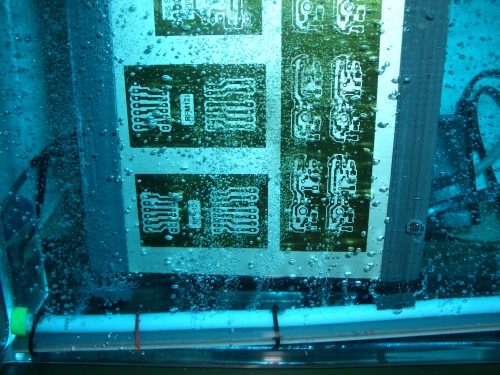 » This picture shows the etching of the PCBs. There is one small PCB for each sensor (consisting of ISF401 and an infrared LED) and an interface PCB containing a PIC16F628 for converting the parallel input of the 8 sensors into a serial bitstream via SPI protocol. |
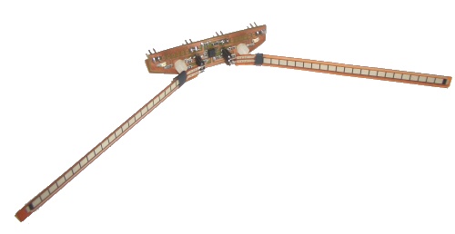 » In addition to the IR sensors, two FlexSensors will be placed on a small board which is mounted at the front of the spider. |
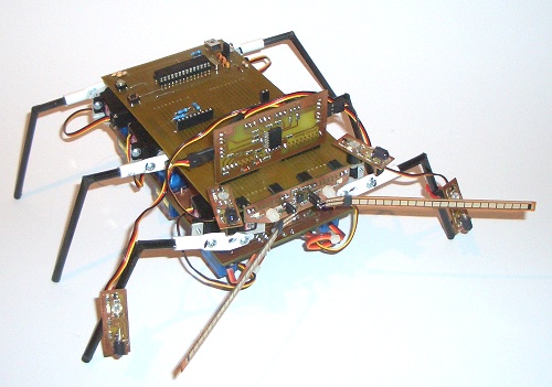 » This picture shows the spider with 4 ISF 401 sensors, interface board and FlexSensors mounted. |
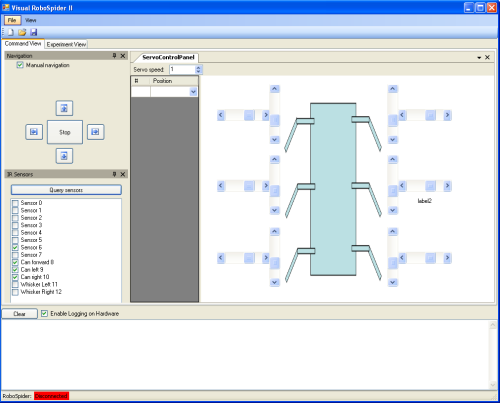 » To monitor the spider's sensors and to control the spider manually I wrote a small C# application that connects to the spider via USB. |
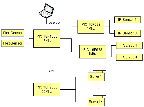 » This is a block diagram of the spiders circuitry. The main PIC (18F2550) communicates with the other PICs via the SPI protocol. Coming soon: 2 flex-sensors for direct obstacle detection (e.g. if the IR sensors fail) and 4 light to frequency converters will be mounted, enabling the spider to walk into dark or bright areas.....stay tuned. |