RGB-Led Controller
Full Color USB LED-Controller
|
Microcontroller: Microchip PIC18F2550 Sensor: 1x DS18S20 temperature sensor Video: Temperature based color control CPU load based color control Screen based color control License: 
The source code of this work is licensed under a Creative Commons License. This project is featured on: pcbheaven.com 320volt.com | ||
 » This project is a full color LED-controller that can be configured via a USB connection. The color of the connected LEDs (common anode only) depends on the selected operating mode:
In the temperature based mode the color changes depending on the temperature measured by the DS1821 sensor. At home I use this mode to light up my radiator depending on its temperature. In the constant color modes, the LED color is constant but can be configured with a C# Windows application via USB. With this application the circuit can also be used to light up the LED in a color that:
| ||
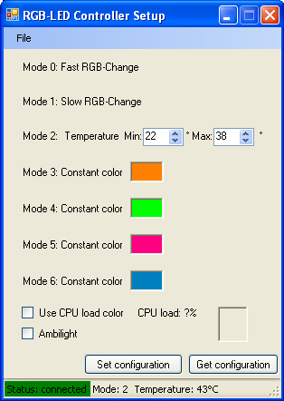 » This is the screenshot of the application. Building the circuit | ||
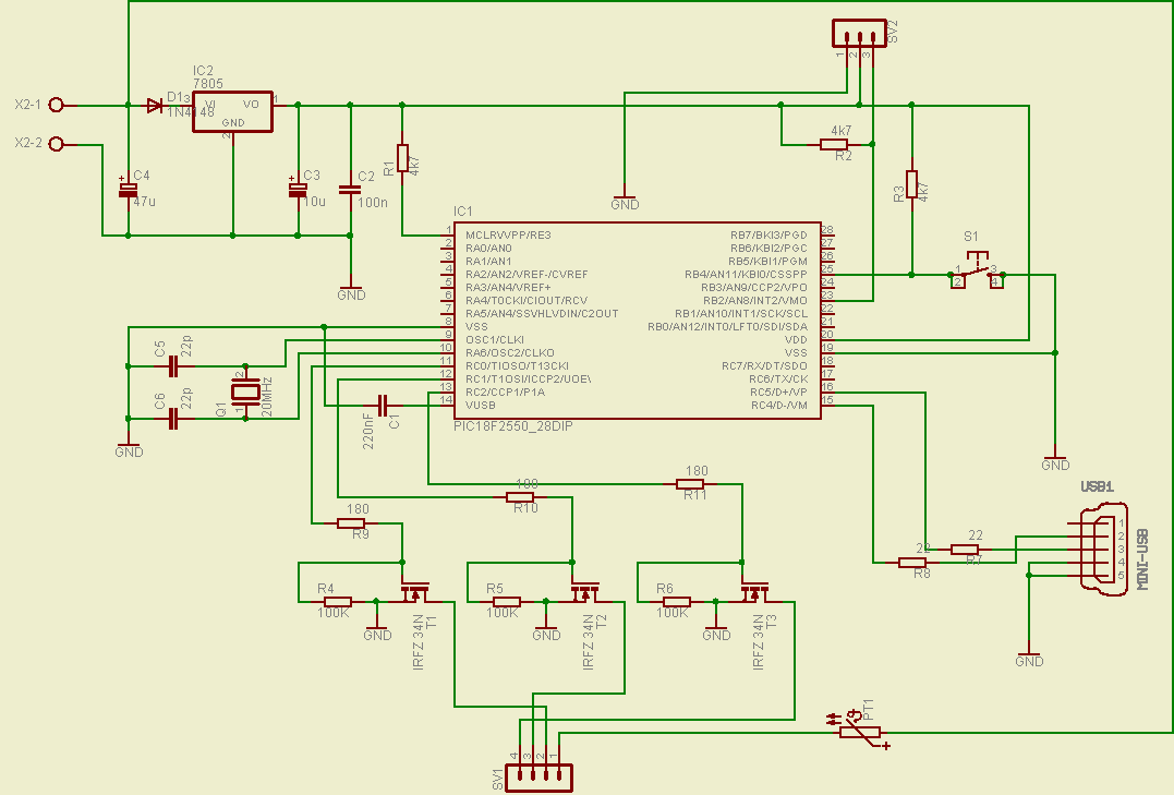
» This is the circuit diagram for the LED controller. The following parts are needed to build it:
| ||

» First of all the PCB needs to be made. The above picture shows the layout of the PCB. The Eagle files are contained in the project's download. | ||
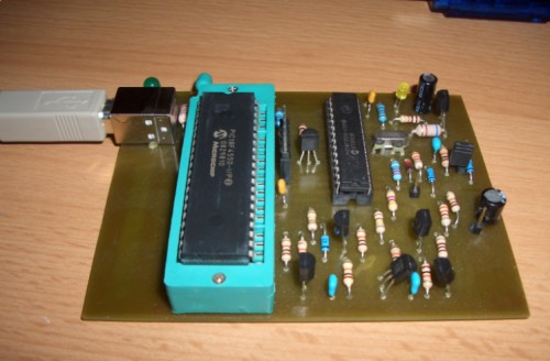
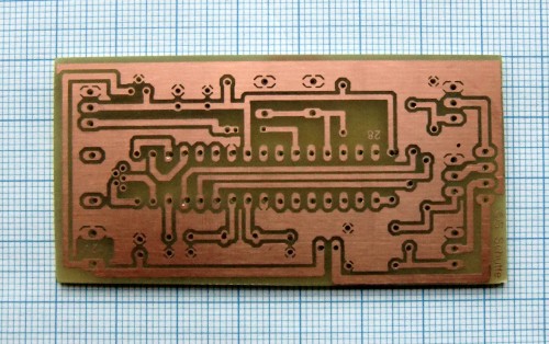 » The finished PCB. | ||
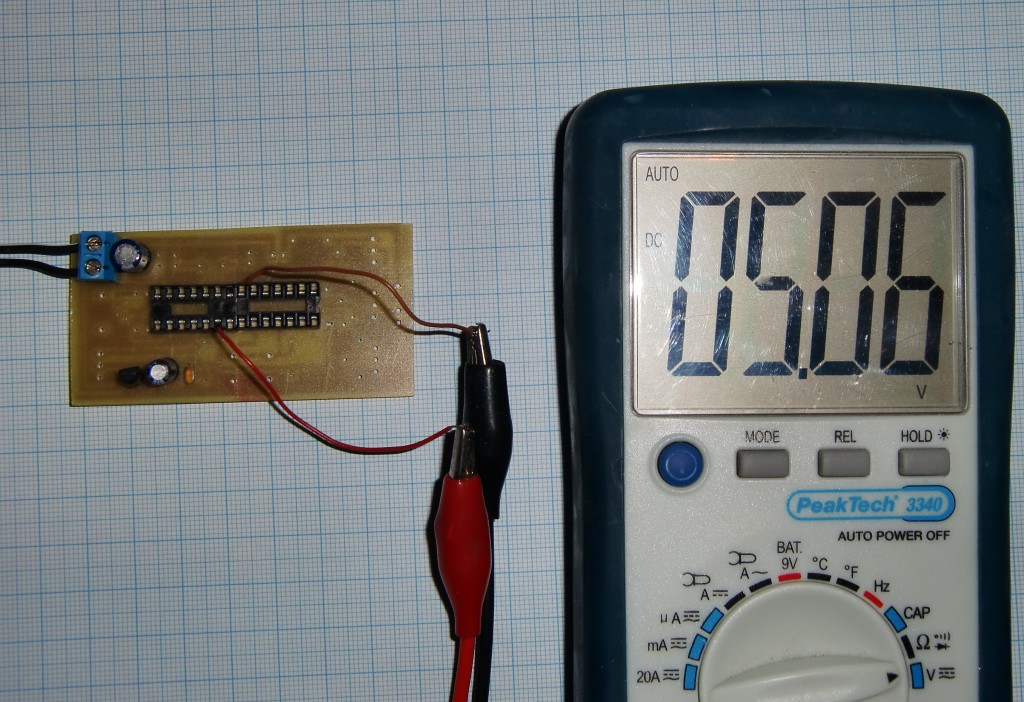
» Next the parts required for providing the 5V for the microcontroller are soldered on the PCB. Once this is done 12V can be supplied and it is checked if 5V are available to the microcontroller (pin8=GND, pin20=+5V). Afterwards the remaining parts can be soldered. | ||
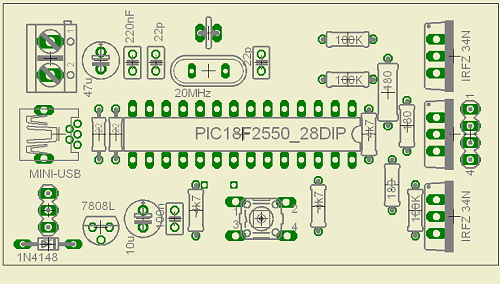 » This picture shows where which parts need to be placed. | ||
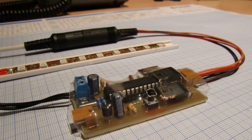
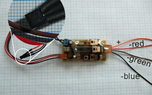 » The above picture shows how the LED-Stripe (common anode) needs to be connected, as well as the wiring for the DS18S20. Programming the PIC | ||
 » Last but not least the PIC needs to be programmed accordingly. This is done in three steps: 1. An unprogrammed PIC 18F2550 is inserted into a burner of your choice (I use a self made Brenner 8 from SPRUT). With this burner the USB bootloader (18f2550_boot_rb4.hex) is burned into the PIC. The bootloader is supplied with this project's download. The config bits are contained in the hex file. 2. Now the PIC is inserted into the circuit built above and is connected via a USB cable to your PC. Now you power up the circuit while holding down the mode-button of the circuit which causes the PIC to enter bootload mode. XP/Vista will ask for a driver. You supply XP/Vista with the driver provided by the Microchip USB Framework installation (C:\Microchip Solutions\USB Device - MCHPUSB - Generic Driver Demo\Driver and inf) and the device is recognized and listed in the hardware manager. 3. Finally, the applications firmware (RGBController.hex) can be programmed into the PIC using the PDFSUSB application supplied by the Microchip USB Framework. Now you can interrupt the power supply of the circuit to let the PIC restart (this time without pressing the mode-button) to let the PIC enter application mode. Now the connected LED(s) should light up. If Windows asks for a driver again please use the one supplied by my project's download (in the folder \ConfigurationUI\WinXP_USBDriver). Please press the mode button now once to let the PIC initialize (this only needs to be done once). If you start the Windows application (\ConfigurationUI\RGBConfigurator\bin\Debug\RGBConfigurator.exe) now you should be able to configure the PIC according to your needs as shown in the first picture above. Please note: For getting it started under Windows 7 please use this version of the software. It uses a newer version of the Microchip USB API DLL (mpusbapi.dll, version 2.6a) and is compiled with the right options to work on 64 bit systems as well. 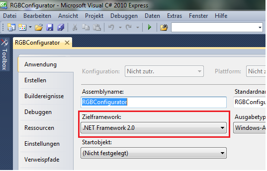 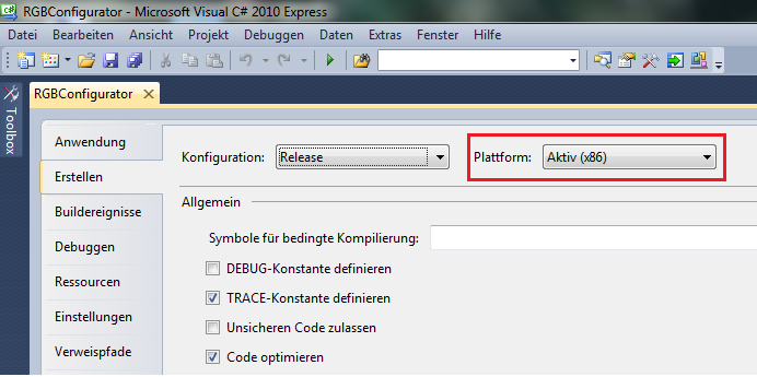
|