Visual PIC
PIC (18F4550) Plugin for StarUML
|
Microcontroller: Microchip PIC18F4550 Requirements: Star UML (available here) Microchip C18 Compiler (available here) .NET Framework 2.0 (not tested with >=3.0) License: 
The source code of this work is licensed under a Creative Commons License. | ||||||||||||||||||||||||||||||||||||||||
|
» Introduction This project is a plugin for the popular Open Source UML/MDA Platform StarUML . The plugin extends StarUML with some new UML elements for modelling, compiling and downloading an application (via USB) to the microcontroller PIC 18F4550. This project does not comprise full modelling capabilities for all peripherials of the PIC but shall serve as inspiration and/or basis for your own extensions. The following picture shows a screenshot of StarUML with a small application model that creates a changing PWM signal. 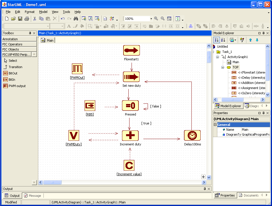 (click to enlarge) Dashed lines show the object flow (the usage of objects by the activities as input or output) while solid lines are used for modelling the program flow, e.g. the transition between different activities. | ||||||||||||||||||||||||||||||||||||||||
|
» Installation After having downloaded the ZIP-File containing all required files (including the source files and some demo projects) here you need to unzip the files into the "modules" folder of your StarUML installation. The resulting structure should look like this: C:\Programme\StarUML\modules\visualPic\.... Now you need to make the plugin accessible to StarUML as a COM object. Therefore you need to execute the batch file "register.bat". Note: The Assembly Registration Tool "regasm.exe" must be in your search path for the batch file to work properly. It comes with the .NET framework and should be lokated in "C:\WINDOWS\Microsoft.NET\Framework\v2.0.50727", for example. Now the VisualPIC AddIn is ready for action. | ||||||||||||||||||||||||||||||||||||||||
|
» Tutorial The following UML elements are available:
Objects like Delay or BitIn/Out offer tagged values for modeling specific properties. | ||||||||||||||||||||||||||||||||||||||||
|
» Some examples 1. Assignment (constant to variable): 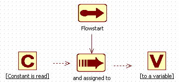 Generates the following code:
2. Assignment (BitIn to BitOut): Port pins are configured using tagged values (via context menu) 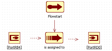 Generates the following code:
3. Branch (IsZero): Branches are configured using the transitions' guard conditions 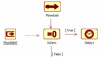 Generates the following code:
3. Branch (IsZero): Branches are configured using the transitions' guard conditions Generates the following code:
| ||||||||||||||||||||||||||||||||||||||||
» The following table shows a complete overview of the allowed number of successor/predecessor objects and activities for each available activity type:
| ||||||||||||||||||||||||||||||||||||||||
» After a UML model of the desired functionality has been created it is required to configure the plugin parameters, so that the code generator and compiler
can do their job. This is done in the configuration dialog available via menu "Tools/Options...".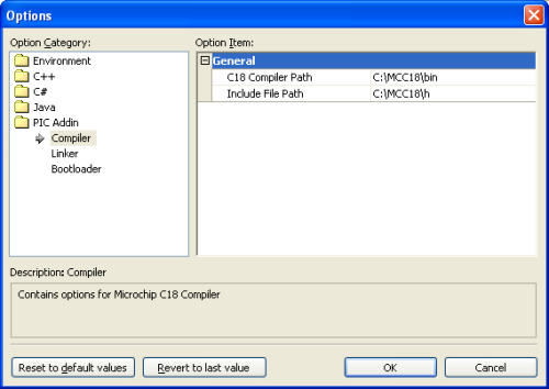 The following parameters have to /can be configured:
| ||||||||||||||||||||||||||||||||||||||||
» Finally the code generator is started using the menu "Tool/PIC/Generate code..." or the context menu of the diagram: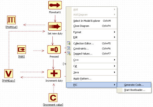
| ||||||||||||||||||||||||||||||||||||||||